Hotel Management Project Rational Rose UML Diagrams
Clases-You can edit this template and create your own diagram.Creately diagrams can be exported and added to Word, PPT (powerpoint), Excel, Visio or any other document. Use PDF export for high quality prints and SVG export for large sharp images or embed your diagrams anywhere with the Creately viewer. Visual Paradigm for UML is an easy-to-use UML tool that supports reverse engineering, code generation, import Rational Rose, export/import XMI, report generator, shape editor, etc. Visual Paradigm for UML is a professional UML tool that supports complete software lifecycle - object-oriented analysis, object-oriented design, construction. Visual Paradigm for UML is an easy-to-use UML tool that supports the latest UML notations, reverse engineering, code generation, import Rational Rose, export/import XMI, report generator, MS Visio integration, IDE Integration with Eclipse, IntelliJ.
Rational Rose: A UML-Based Design Tool. Rational Rose for Database Design. Rational Rose is one of the modeling tools used in the industry to develop information systems. It was acquired by IBM in 2003. As we pointed out in the first two sections of this chapter, a database is a central component of most information systems. Introduction to Rational Rose 1. An introduction 2. ROSE = Rational Object Oriented Software Engineering Rational Rose is a set of visual modeling tools for development of object oriented software. Rose uses the UML to provide graphical methods for non-programmers wanting to model business processes as well as programmers modeling application logic. Facilitates use of the Unified Modeling.
AIM: IMPLEMENTATION OF HOTEL MANAGEMENT USING RATIONAL ROSE UML DIAGRAMS
THEORY:
Rational Rose provides support for two essential elements of modern software Engineering: component-based development and controlled iterative development.
While these concepts are conceptually independent, their usage in combination is both natural and beneficial.
Rational Rose’s model-diagram architecture facilitates use of the Unified Modeling Language (UML), Component Object Modeling (COM), Object Modeling Technique (OMT), and Booch‘93 method for visual modeling. Using semantic information ensures correctness by construction and maintaining consistency.
Modeling with Rational Rose
Rational Rose is the visual modeling software solution that lets you create, analyze, design, view, modify, and manipulate components. You can graphically depict an overview of the behavior of your system with a use-case diagram. Rational Rose provides the collaboration diagram as an alternative to a use-case diagram. It shows object interactions organized around objects and their links to one another. The state chart diagram provides additional analysis techniques for class switch significant dynamic behavior. A state chart diagram shows the life history of a given class, the events that cause a transition from one state to another state, and the actions that result from a state change. Activity diagrams provide a way to model a class operation or the workflow of a business process.

Notation plays an important part in any application development activity—it is the glue that holds the process together. UML provides a very robust notation, which grows from analysis into design.
UML diagrams
• Instead of the Context, Data-Flow and Entity-Relationship Diagrams used in Structured Analysis, UML produces 9 types of diagrams
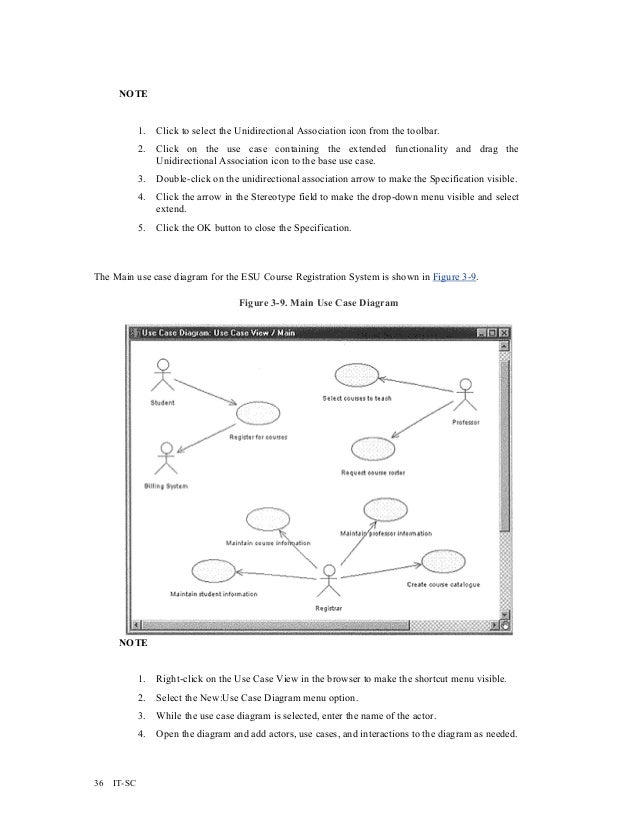
Use cases are best discovered by examining what the actor needs and defining what the actor will be able to do with the system; this helps ensure that the system will be what the user expects.
– Sequence Diagram
A sequence diagram is a graphical view of a scenario that shows object interaction in a time-based sequence—what happens first, what happens next. Sequence diagrams establish the roles of objects and help provide essential information to determine class responsibilities and interfaces. Sequence diagrams are normally associated with use cases.
This type of diagram is best used during early analysis phases in design because they are simple and easy to comprehend. A sequence diagram has two dimensions:
Typically, vertical placement represents time and horizontal placement represents different objects.
– Collaboration Diagram
A collaboration diagram is an interaction diagram which shows the sequence of messages that implement an operation or a transaction. These diagrams show objects, their links, and their messages. They can also contain simple class instances and class utility instances. Each collaboration diagram provides a view of the interactions or structural relationships that occur between objects and object-like entities in the current model.
– State chart Diagram
State chart diagrams model the dynamic behavior of individual classes or any other kind of object. They show the sequences of states that an object goes through, the events that cause a transition from one state or activity to another, and the actions that result from a state or activity change.
State chart diagrams are closely related to activity diagrams. The main difference between the two diagrams is state chart diagrams are state centric, while activity diagrams are activity centric. A state chart diagram is typically used to model the discrete stages of an object’s lifetime, whereas an activity diagram is better suited to model the sequence of activities in a process.

– Activity Diagram
An activity represents the performance of “task” or “duty” in a workflow. It may also represent the execution of a statement in a procedure. An activity is similar to a state, but expresses the intent that there is no significant waiting (for events) in an activity.
– Class Diagram
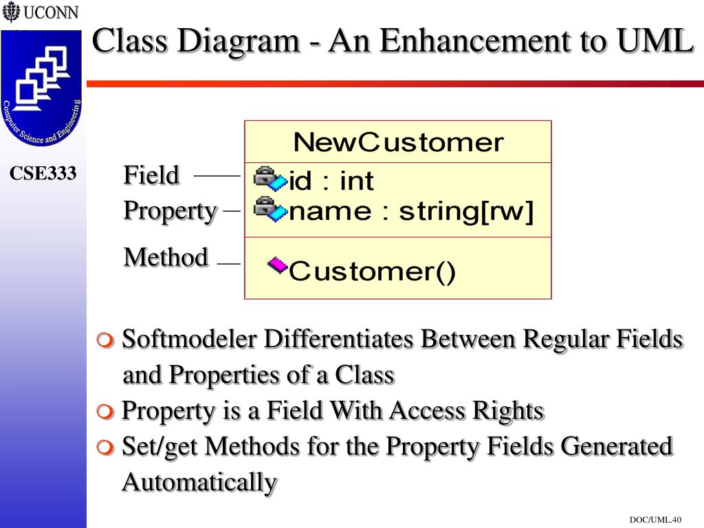
A Class Specification displays and modifies class properties and relationships. Some of the information in the specification can also be displayed inside class icons.
Rational Rose software, free download For Uml Diagrams Online
If a field does not apply to a particular class type, the field is unavailable and you cannot add or change information in the field.
– Object Diagram
An Object Flow Specification allows you to display and modify the properties and relationships of an object flow on an activity diagram.

– Component Diagram
A component diagram shows the physical dependency relationships (mapping to a file system) between components—main programs, subprograms, packages, and tasks—and the arrangement of components into component packages.
– Deployment Diagram
A deployment diagram shows processors, devices, and connections. Each model contains a single deployment diagram that shows the connections between processors and devices, and the allocation of its processes to processors.

We implemented the hotel management using UML diagrams described above in rational rose.
Rational Rose software, free download For Uml Diagrams Pdf
Other Projects to Try:


